
Custom Ford Capri Atlas axle
During the first stage of the build, when Capri supposed to be just a show car, I wasn’t even looking at the drive train. I just want it to look pretty on the outside, but the truth is, I didn’t know anything about mechanics. It eventually got its turn. The following build is a process that was going on for a couple of years, like many previous ones. Please note I’m not an expert on this matter, only an enthusiast doing the best he can, so please don’t take this information and solutions presented here for granted. With that said, let’s start.

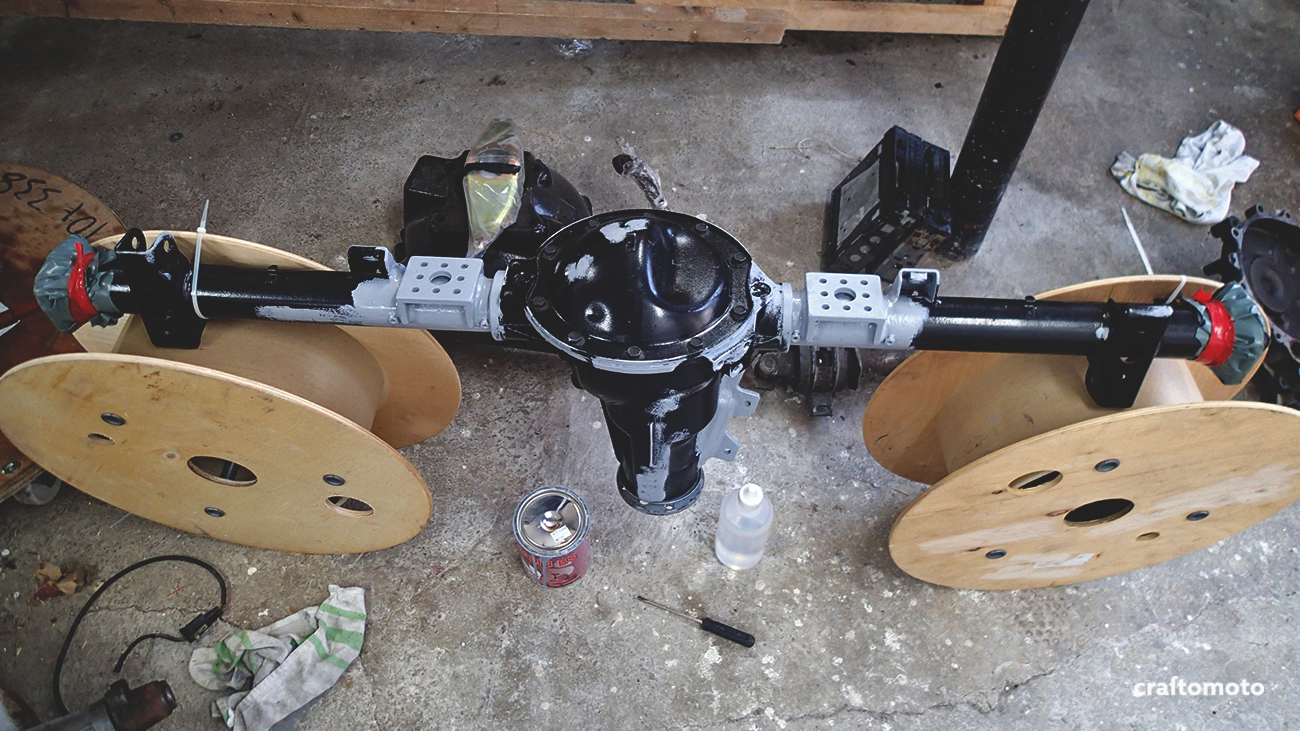
The first thing I have selected was the axle, after I scavenged a couple of them. My choice was 1.6 3.75 atlas axle, so I can get a little more power at the low speeds and optimal for hauling a trailer at 90 km/h. The maximum speed will be affected, but since this car is built for traveling, we’re not in a hurry to get anywhere.

Everything was taken to the sandblasters to remove the 40 year old rust and gunk. Also, they put a thin layer of primer.

Among the other things, the rear ARB parts were hand cleaned, chemically derusted and zinc plated.

With this custom made tool, wheel bearing retainer collars were installed to my half-shaft. I wasn’t too crazy about doing it myself, since you get only one chance while securing the bearing holder, so I left this to the professionals that have done it a hundred of times.

The gears were removed and new seals have been put into place.

Everything sealed and closed.

Also, I started working on the brakes.

I removed the surface rust and cleaned discs with the turning machine.

Little spray paint protection and it looks like new. But to be honest, I stored that set for the emergency spares and used a brand new set at the end.

Front and rear Sierra calipers were in a really poor shape.

Everything was disassembled, holes were plugged, sand blasted and painted with thermal paint.

The local company reassembled the whole thing back together from two sets of calipers, and replaced a few broken and badly worn out pieces, so it was a good call to use professional service on that subject. I also refurbished the master cylinder from Sierra.

I bought the conversion adapters from Epytec in the meantime, and dry fitted them.

I’m used to transport all the parts in my small Mitsubishi.

The mounts for the axle electric motor system have been laser cut from the high quality steal and then welded.
Some more primer was added.

The brake lines were also added to the schedule. This was the first totally failed attempt, because I didn’t put the flexible pipe to the caliper. Everything was scrapped, but than again I have started to get into the plotting the brake route and bending the brake line.
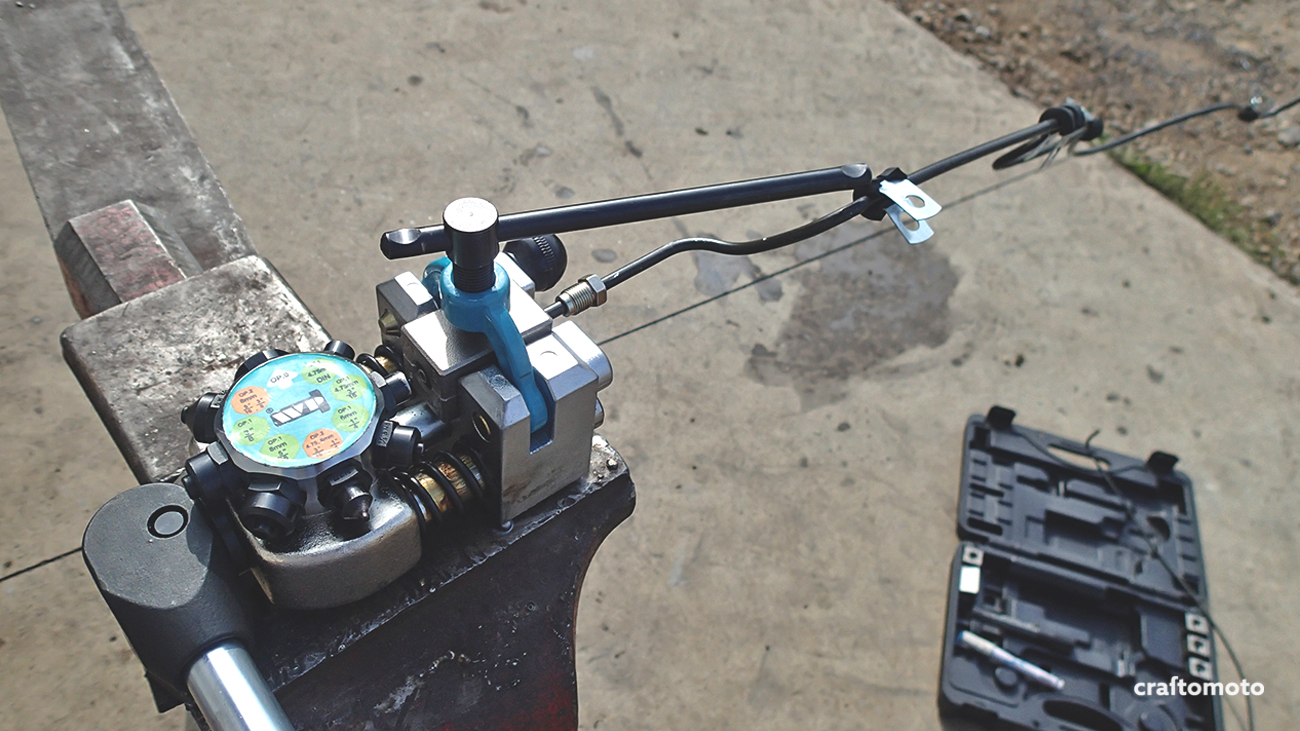
All the most important things I’m doing under the professional supervision, just in case the theory and the experience differs somewhat, so this was no different. The brake lines were flared by this professional tool.
Because of the regulations, I needed to use steel pipes instead of widely used copper, so this tool was handy.

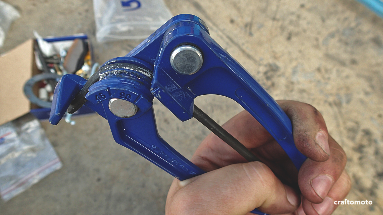
Every learning curve is difficult. Here’s the thing with this pipes – once you bend them to the wrong side there is no turning back, so I spent few days doing the same brake line over and over again, until I managed to make it right.
Some parts were laser cut and TIG welded, these will eventually hold the brake lines.

Didn’t wan’t to use some kind of zip tie solution, so I made a bracket for the emergency brake cables. Instead of bending steel, the square pipe was cut to make two U profiles.

Oh yeah, there were two attempts of making the brackets. The first one was hand filed, and the second one was machine drilled to make it more precise.

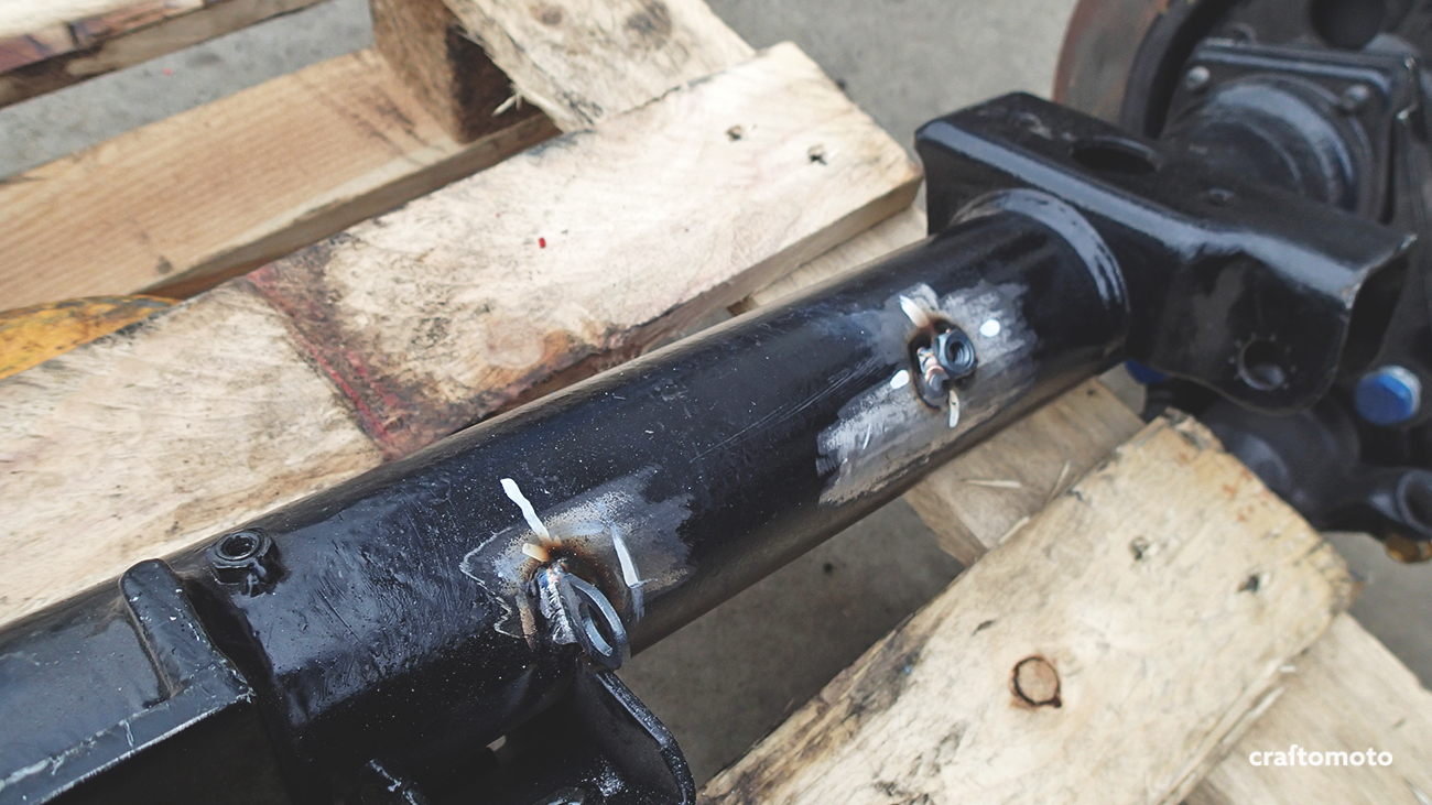
The adapters have been TIG welded to the axle after lots of fiddling.

Again – some more primer.

There were some small issues that needed attention like grinding the edge of the adapters because of the pipe radius.

I decided to paint the pipe in red. Just so I can see if there are any issues during the road with it. But after few thousand kilometers, I think it will be all black from the dirt anyway. The red water based paint just didn’t hold, so the procedure was needed to be done all over again with a different paint, after the bad coating was removed. Luckily, that wasn’t too tough.

All painted all over again. Now you can finally see the complete brake line.

Everything is ready for the final assembly. I have been using the manual and correct torque settings to reassemble the whole thing.

I also added some thread lock to the bolts just in case. In the meantime, I realized the brake lines were single flared instead double flared, so I decided to do the brake lines all over again. Also didn’t really like the red color, so I left the factory coating and just sprayed clear coat to protect it little more.

The rear axle in its splendid glory.

Still not yet tightened, also I left the U bolts uncut since I don’t know if I’ll need the lowering blocks.

Since I have closed wheel nuts and long studs, the PVC pipe was cut to temporary hold the disc in place.

Brake cable holders in action.

Nice to see how the brake line follows the curve.

A detail shot.

Brake line junction, it’s more difficult than it looks or as difficult as it looks.

Rear electric motor mounts are ready and waiting for the future!
For those who are asking themselves: „electric motor mount what?“ – the idea was to have two electric motors next to the combustion one. One in the front, running on ultra – capacitors and connected to the crankshaft via belt pulley, so the car can essentially become a hybrid, and the other one on the rear axle directly connected to the differential, draining the batteries from the caravan. When the car is in neutral, it should enable full electric drive.
If you like what you see, you can always follow us on Facebook and Instagram 
–


